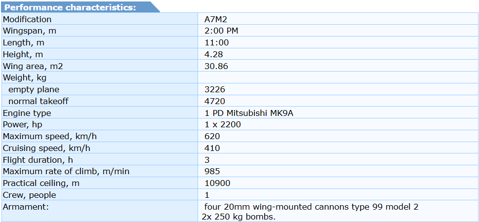
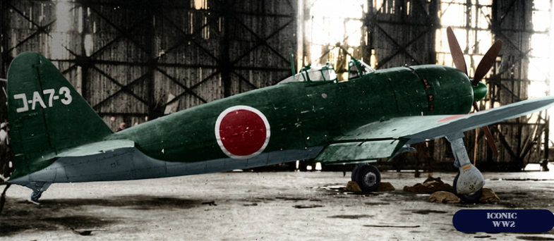
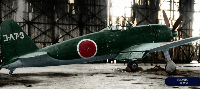
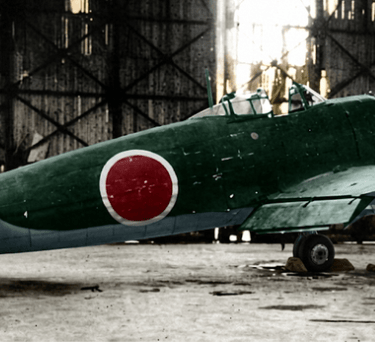
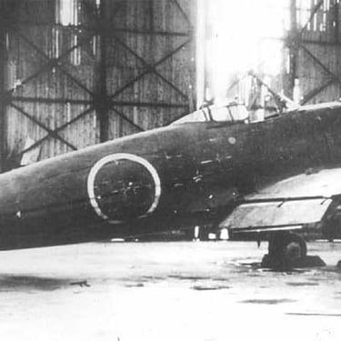
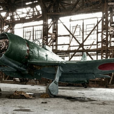
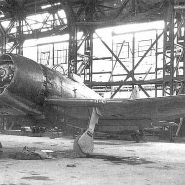
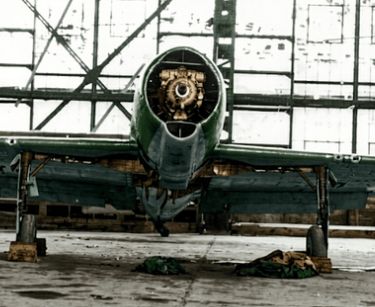
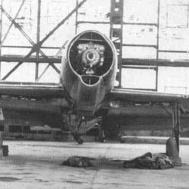
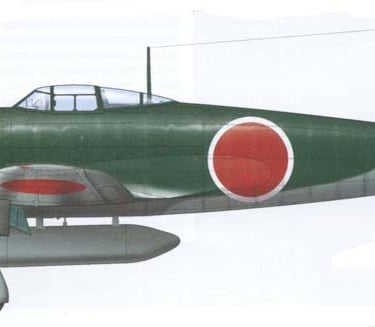
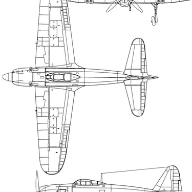
Mitsubishi A7M Fighter
Developer: Mitsubishi
Country: Japan
First flight: 1944
Type: Carrier-based Fighter aircraft
In 1940, immediately after the new Zero carrier-based fighter was adopted by Japanese naval aviation, work began on a next-generation fighter. This work resulted in the 16-Shi specifications, formulated in early 1941. Mitsubishi, which had excelled in its work on the A6M, was tasked with implementing these requirements.
However, the company was fully booked at the time and could not immediately begin developing the new aircraft. Mitsubishi's engineering and technical capabilities proved insufficient—its peacetime production capacity was clearly insufficient for wartime work.
In April 1942, Naval Aviation Headquarters again contacted Mitsubishi, demanding that work begin immediately on the revised technical specifications for the 17-Si.
In addition to the deadline, the technical specifications included specific performance requirements for the future aircraft. The maximum speed at 6,000 meters was no less than 640 km/h, the time to climb from 6,000 meters was no more than 6 minutes, the flight time at 400 km/h was no less than 2.5 hours, a reserve for a half-hour flight at maximum speed, a maximum dive speed of 830 km/h, maneuverability no worse than that of the A6M3 model 32, and armament consisted of two 20 mm cannons and two 13.2 mm machine guns.
The requirements for the aircraft under those conditions were extremely stringent. Meeting these requirements would have resulted in the creation of the world's finest fighter. Engineer Jiro Horikoshi's team officially received the order on July 6, 1942. Consequently, a year and a half elapsed between the completion of the A6M and the start of work on the A7M—as it later turned out, this delay was fatal. The new aircraft was given the factory designation M-50 and the proper name "Reppu."
To meet the requirements, Jiro Horikoshi decided to equip the future aircraft with a "future" engine—the A-20 eighteen-cylinder radial engine, then under development at Mitsubishi. The A-20's expected engine parameters could provide the aircraft with the necessary qualities. The engine's starting power was 2,100 hp (1,545 kW) at 2,900 rpm, and at an altitude of 2,000 meters, its power was 1,900 hp (1,398 kW) at 2,800 rpm. At an altitude of 6,000 meters, the engine developed 1,760 hp (1,295 kW). However, due to technological difficulties, the engine was not expected to be ready before the spring of 1943. Therefore, in order not to delay the work that had begun late, in September 1942, the Naval Aviation Headquarters ordered the installation of the Nakajima Homare-22 (NK9H) engine on the new aircraft. This engine developed 1,500 hp (1,104 kW) at an altitude of 6,000 meters.
Mitsubishi engineers were overwhelmed by the work of finalizing the also-late J2M Raiden interceptor and upgrading the rapidly aging A6M, so assembly of the first M-50 Reppu prototype did not begin until April 1944. The new aircraft was officially named "17-Shiki-kanjo-sentoki Reppu"—"Naval 17-Shi Carrier-Based Fighter Reppu" (A7M1). The prototype was equipped with a Homare-22 engine. The aircraft's design featured several technical innovations new to Japan: self-sealing fuel tanks, an armored pilot's seat, and hydraulically folding wingtips. The folding wings were an important design element, as the aircraft had impressive dimensions for its class. The wingspan was 14 meters, and the area was 30.86 m². These dimensions—one and a half times larger than the A6M—were necessary to meet the technical specifications. The aircraft needed to achieve high speed, requiring a powerful but large and heavy engine. The aircraft needed to remain airborne for three hours, requiring space for large fuel tanks. The new fighter's maneuverability had to be comparable to its predecessor, requiring a large wing area.
On May 6, test pilot Eisaki Shibayama took the controls of the prototype and performed the aircraft's maiden flight. During the takeoff run, some landing gear flaws were revealed, but overall, the aircraft was a success. Testing continued over the next three weeks, addressing any issues. Military pilots then took the aircraft into their own hands. Reviews of the fighter were positive, particularly noting its excellent stability and controllability, as well as maneuverability that was even better than that of the A6M. This excellent maneuverability was achieved through additional flaps, which the pilot could deploy during flight by pressing a button on the control column. While the pilot pressed the button, the additional flaps remained extended, but as soon as the button was released, the flaps automatically retracted. However, other requirements for the aircraft were not met. Since the Homare-22 engine produced only 1,620 horsepower at an altitude of 6,400 meters, the aircraft was capable of handling a maximum of 1,500 hp. (1192 kW), so the aircraft developed a maximum speed of 555-575 km/h, and gained an altitude of 6000 meters in 10-11 minutes.
Since the requirements were not met, on July 30, 1944, the Naval Aviation Headquarters ordered the suspension of work on the aircraft. Assembly of the third, fourth, fifth, and sixth prototypes was also suspended.
The test results were not surprising to Jiro Horikoshi, who had already stated before the first flight that the aircraft would not reach the required speed due to its underpowered engine. Therefore, Horikoshi received permission to install a Mitsubishi MK9A engine in the sixth prototype. This was more powerful than the A-20, producing 2,200 hp (1,619 kW) at takeoff. The prototype with the new engine was designated A7M2. The MK9A's diameter was 1,230 mm, 50 mm larger than the NK9. The propeller remained the same—a four-bladed variable-pitch propeller with a diameter of 3.60 meters.
Because the new engine was larger, the engine mount and forward fuselage had to be redesigned. This work was completed in early October 1944, and on October 13, the new prototype took to the air. Although the engine didn't deliver its designed power, the aircraft performed close to the design specifications. It was projected that, after installing armament, the aircraft would be able to reach a speed of 627 km/h (390 mph) at an altitude of 6,000 meters (19,800 ft). Given its good maneuverability, this would have given the Japanese aircraft an advantage over the American F6F-5 Hellcat and F4U-1D Corsair, which achieved roughly the same speed.
Since the test results were promising, the military decided to begin serial production of this aircraft, which by then had received the designation "Reppu Model 22 Naval Carrier Fighter" (A7M2). Production was planned to begin at two Mitsubishi-owned factories: the Oe Aircraft Plant in Nagoya and the Nankai Plant in Osaka.
The A7M2 model 22 aircraft were to be equipped with two armament options: four 20 mm Type 99 model 2 cannons or two 20 mm cannons and two 13.2 mm Type 3 machine guns. The armament was installed in the wings outside the propeller plane.
In December 1944, an earthquake struck Nagoya, and subsequent B-29 raids completed the factory's destruction. It became clear that plans could not be fulfilled, especially since the Daiho Engine Plant, which produced the MK9A engines, had also been hit. Misfortunes continued to plague the Japanese. A landing accident completely destroyed the second prototype. The first, third, and fifth prototypes were destroyed by American bombs. By the end of the war, only two prototypes—the fourth and sixth—survived. The third A7M2 was the first and only production aircraft.
Meanwhile, the Naval Aviation Headquarters developed the 17-Ci B specification for a land-based interceptor fighter, to be built on the A7M2 platform. The specifications were submitted to Mitsubishi in February 1944. The interceptor's primary focus was on a high rate of climb and a high maximum speed at high altitude. The aircraft was armed with four 30mm Type 5 cannons mounted in the wings. Two more cannons, facing rearward and upward, were to be mounted behind the cockpit.
To meet these requirements, the aircraft's design had to be completely redesigned. First and foremost, the wing's profile had to be increased to accommodate such powerful armament. The landing gear was reinforced, with larger-diameter and wider wheels to allow the aircraft to take off from airfields. As a result, the wing's chord was increased near the fuselage. The fuselage itself was also reinforced, and cannon mounts were installed there. The new interceptor was designated "Naval 17-Si B experimental fighter-interceptor Reppu Kai model 34" (A7M3-J "Reppu" Kai model 34).
The aircraft was planned to be equipped with a turbocharged MK9A-Ru engine. It was projected to reach a speed of 648 km/h at 10,000 meters, reaching that altitude in 15 minutes.
Complete documentation for the aircraft was prepared in a very tight timeframe, and by February a full-scale mockup had been assembled and presented to a commission from the Naval Aviation Headquarters. The headquarters approved serial production of the interceptor and developed a construction schedule for the prototype, which was scheduled for completion in October 1945. Externally, the interceptor differed from the A7M2 in its longer fuselage, which additionally housed a compressor. The compressor was located in the lower fuselage at the height of the pilot's seat. A long hose connected the compressor to the exhaust system. The compressor's air intake was located above the engine and also connected to the compressor via a long duct. Compressed air was supplied to the engine through a large radiator located behind the engine. A 200-liter tank for a water-methanol mixture was also located in the fuselage, forward of the firewall. The mixture was injected into the engine during boost.
Since the designers foresaw difficulties in fine-tuning the turbocharger—and the Japanese had little experience with such devices up to that point—a "substitute" interceptor, the A7M3 Model 23, was designed. The Model 23 was powered by an MK9S engine with a three-stage compressor, which extracted power from the engine shaft via a step-up gear (multiplier). Unlike the A7M3-J, which was radically redesigned, the A7M3 Model 23 closely resembled the A7M2. Distinctions included non-folding wings and an additional fuselage fuel tank, like the A7M3-J. The pilot's head was to be protected by bulletproof glass. The A7M3 Model 23 was armed with six Type 99 Model 2 20mm cannons. Theoretical calculations showed that the aircraft would reach a speed of approximately 642 km/h at an altitude of 8,700 meters. The first prototype of this aircraft was planned to be completed in December 1945.
After the end of hostilities in the Pacific Ocean on August 15, 1945, both projects were cancelled. At the end of the war, the Naval Aviation Headquarters issued Technical Specification 20-Ci A to Mitsubishi for the construction of the A8M "Rifuku" fighter. The A8M design was based on the A7M3-J. This project did not pass the design research stage before the end of the war.
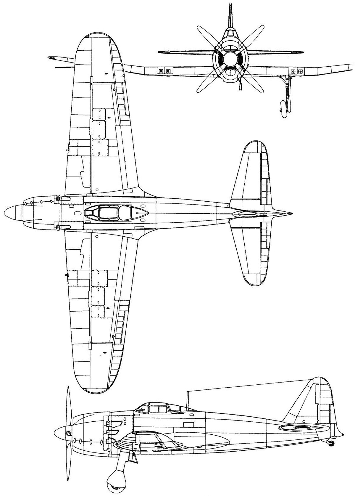
The Mitsubishi A7M is a single-engine, single-seat, carrier-based fighter aircraft of all-metal construction with fabric-covered ailerons and rudders, designed as a cantilever low-wing monoplane.
The fuselage consisted of two sections: the forward section (engine compartment) and the rear section (fuselage proper). The fuselage had a closed structure and extended from the firewall to the last frame (number 19), which was located at the level of the stabilizer trailing edge. The fuselage framework consisted of 19 frames and two half frames. The main load-bearing elements of the fuselage were the second and fourth frames, which formed the structure to which the pilot's seat and anti-coupling frame were attached. Both load-bearing frames were stamped channels with reinforcing plates. Frames 8 and 14, the points where the fuselage was divided into technological sections, also had a reinforced structure. The frames were connected by closed-section stringers, to which the hull skin was riveted. Auxiliary stringers and duralumin angles ran between the main stringers, reinforcing the skin. The firewall was made of thin sheet steel. The forward fuselage was integral with the wings. The upper wing skin inside the fuselage served as the cockpit floor. The wing spars connected to frames 2 and 4. The skin was riveted to the frames and stringers with countersunk rivets. The rear fuselage section, beginning behind frame 14, was integral with the tailplane. The last frame (frame 19) simultaneously served as the main stabilizer spar and as the attachment point for the support wheel. The rear fuselage was enclosed by a fairing stamped from sheet steel. The fairing was attached to half-frame 19a and to the supporting elements of the stabilizer.
The first frame contained four engine mounts. The engine mount consisted of steel tubing, with a ring at the front of the frame to which the engine was attached. Four pairs of tubes were welded to the ring, connected in a "V" shape. The top of each "V" connected to the first frame.
The wings were trapezoidal, two-spar structures with rounded tips, covered with smooth duralumin sheet. The skin was attached with countersunk rivets. The maximum wing chord was 3,000 mm with a thickness of 430 mm at the axis of symmetry. Each wing, in addition to the two spars, consisted of 29 ribs spaced at varying distances from one another. The ribs were also connected by a stringer system, reinforcing the skin. The wing folded along the 22nd rib. A hydraulic system was used to fold the wings. Each wing had space for a fuel tank and weapons. The wheel well was located forward of the front spar. The wings were three-piece, with a horizontal center section extending to the 14th rib and consoles elevated at 4°20′. The junction of the wing and the body was profiled with a fairing, which reduced the turbulence of the air flow.
The ailerons had a metal frame and fabric covering. Their span was 3,315 mm, with a maximum chord of 450 mm. They could deflect 35° upward and 25° downward. When the wing was folded, they broke approximately mid-section. The ailerons were suspended by four hinges to the rear auxiliary wing spar. The ailerons were controlled by a control wheel, which could deflect 20° in either direction. From the control wheel, force was transmitted via a system of pushrods and bellcranks. Each aileron had a counterbalance valve, which could be adjusted within a +20° range during flight using a screw located on the cockpit wall.
The flaps were slotted, all-metal, and spanned 2,740 mm. They were located between the 6th and 15th ribs. At the cockpit, the flaps were 700 mm wide. Each flap was attached with three hinges. When fully extended, the flaps deflected downward to 35°. The flaps were controlled by a booster and rocker arms. Aft of the flaps were additional flaps, which deflected downward to an additional 35°. These flaps were extended by pressing a button on the control column and increased the aircraft's maneuverability. The empennage was a cantilever metal structure with fabric-covered control surfaces. It was integral with the rear fuselage section, with the exception of part of the stabilizer. The stabilizer had a two-spar design and spanned 5.60 meters. The stabilizer profile was symmetrical, with a maximum profile thickness of 210 mm. The stabilizer was set at a constant angle of -1°. Two counterbalanced elevators were attached to the rear stabilizer spar. Each elevator had a trim tab that could be adjusted up and down 20°. The elevators themselves could be adjusted up 40° and down 30°. The elevators were controlled by a control wheel, which deflected 14°10' forward and 24° aft (the elevators were in a neutral position when the control wheel was adjusted back 1°).
The vertical stabilizer had a symmetrical profile and was angled 2° to the left. A partially balanced rudder, capable of deflecting 40° in either direction, was suspended from its rear spar (frame 19 of the fuselage) by three hinges. The rudder had a trim tab that deflected 20° in either direction. The trim tab consisted of two parts: one was adjusted on the ground, and the other could be adjusted in flight. The rudder was operated by a foot lever (pedals), deflecting 30° in either direction. Force was transmitted to the rudders via a system of rods.
The landing gear was of the classic tailwheel design. The main landing gear was a single-strut design with pneumatic-hydraulic shock absorption. The landing gear was retracted hydraulically. The track was 4,235 mm. The shock absorber travel was 200 mm, of which 130 mm was the sag at full load. The wheel well had a four-piece cover. One cover was located near the landing gear strut attachment, the second and third covers were attached directly to the landing gear strut, and the fourth cover was located on the wing closer to the fuselage. The last cover was secured with a system of levers that slammed it shut when the landing gear was retracted. The second cover was attached to the landing gear strut above the shock absorber, and the third cover was attached below the shock absorber. A scale was applied to the second cover, indicating the sag of the shock absorbers (the third cover overlapped the scale). The main landing gear was equipped with hydraulic brakes, activated by buttons on a foot lever in the cockpit. The wheels measured 700 x 200 mm. When retracted, the landing gear was secured with locks and did not require constant hydraulic operation.
The tail wheel was mounted on a fork, which also had its own shock absorber. Its dimensions were 200 x 75 mm. The tail landing gear strut could be adjusted through a 60° range in either direction. The tail wheel was retracted using a power steering system, which also served as a shock absorber.
The power plant consisted of one eighteen-cylinder air-cooled double-star Nakajima NK9A Homare-22 (Ha-45-22) engine on the A7M1 or an eighteen-cylinder Mitsubishi MK9A (Ha-43-11) engine on the A7M2, MK9A-Ru (Ha-43-11-Ru) on the A7M3-J or MK9S (Ha-43-31) on the A7M3.
The NK9K, MK9A, and MK9S engines were mated to compressors, which extracted engine power through a multiplier. The compressors increased the pressure in the engine intake manifold. The MK9S engine was equipped with a two-speed, three-stage compressor, unlike the MK9A, which had a single-speed compressor. A planetary gear was located in the front of the engine, transmitting torque to the propeller shaft. The propeller was a four-bladed Sumitomo variable-pitch propeller with a diameter of 3600 mm. The central section of the propeller was covered by a spinner with a diameter of 600 mm.
The fuel system consisted of a fuel pump located near the engine, a filter system, and an auxiliary manual fuel pump located in the cockpit near the pilot's seat. The fuel system also included several fuel tanks of varying capacity, which varied depending on the aircraft model. All fuel tanks were self-sealing. To increase flight time, the aircraft could carry 350-liter drop tanks under the wings.
The lubrication system consisted of a 125-liter oil tank located in the rear of the engine compartment near the top of the firewall, gear pumps located near the engine, and an oil cooler. The oil cooler had its own air intake located at the bottom of the cowling. The propeller pitch control system had its own circuit and its own electrically driven gear pump.
The hydraulic system was used only to operate the landing gear and flaps. Pressure in the system was generated by a small gear pump, which drew power from the engine and had a relief valve.
The pilot's cabin occupied the space between frames 1 and 5. It housed a height-adjustable pilot's seat, stamped from duralumin sheet, and a suite of flight, navigation, and engine control instruments. The cabin had a floor. A control stick was located in front of the seat. To control the rudder, the pilot used a foot lever with pedals that activated the main landing gear brakes.
The cockpit was topped by a canopy made of organic glass. Behind the seat headrest was a cowling guard and an armored backrest. Inside the cockpit was a Type 98 or Type 4 reflex sight.
The cockpit also contained oxygen equipment for high-altitude flight. The oxygen tanks were located in the rear fuselage. Behind the seat were a HF transceiver, a radio direction finder, and a battery. A step on the left side of the fuselage allowed the pilot to climb into the cockpit. Armament consisted of four wing-mounted 20mm Type 99 Model 2 cannons.
The ammunition belts for the Type 99 Model 2 Modification 4 cannons were stored in box magazines, accessible through hatches on the upper wing surfaces. These same hatches allowed the aircraft's armament to be removed. Spent cartridges were ejected through special openings on the lower wing surfaces.
Mitsubishi A7M “Reppu” fighter